


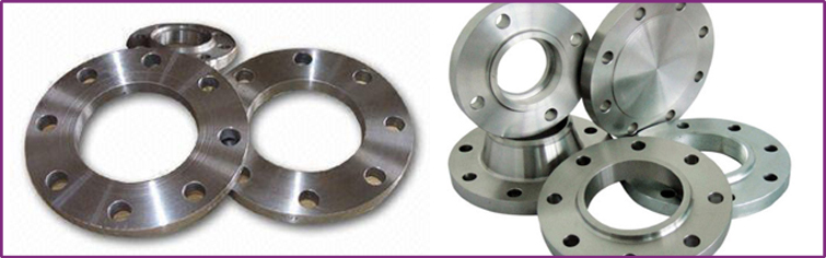
SLIP ON FLANGES
A Slip-On Flange is bored sightly larger than the outer Diameter of the matching pipe. The pipe slip into the flange prior to welding both inside and outside to prevent leaks.The British standard flanges manufactured by us pertain to all Standards like BS10 1962 Table D,E,F,H IS 6392 Table 5,17,26 IS 1538 in slip. These are manufactured using mild steel both in slip-on and blind type. Our quality slip on flanges are ideal for lower pressure applications. Their ease of fitting and welding reduces fabrication costs. Our professional engineering team is involved in innovating durable and high-quality products to cater to our clients' needs.
The flange is slipped over the pipe and then welded both inside and outside to provide sufficient Strength and prevent leakage. This flange is used in preference to weld necks by many users because of its lower cost and the fact that less accuracy is required when cutting pipe to length.
Sizes for Slip On Flanges
All Slip On Flanges are available available in sizes from 1/4” through to any size.
Wall Thickness for Slip On Flanges
Schedule 5s through to Schedule XXS and heavier.
Dimensions
Diameter : 1/2" à 24"
Pressure class : 150# - 300# - 600# - 1500#
Dimensions and Pressure Ratings for Slip On Flanges:
- ANSI, MSS- SP-44, BS3293, API 605 150lb through to 2500lb
- Flange Facings: Raised Face, Ring Type Joint, Large Tongue & Groove, Small Tongue & Groove
- BS4504 - PN6, 10, 16, 25, 64
- BS10 - Table D, E, F, & H
- DIN Standards
Variations
Face finish : Raised face (RF) - Flat face (FF) - RTJ
Variations : Reducing Slip On - Orifice Slip On
Standards
ASTM A182 - ASME SA182 - 'Standard Specification for Wrought Austenitic Stainless Steel Piping Fittings'
ASME B16.5- 'Pipe Flanges and Flanged Fittings'
ASME B16.36 -'Orifice Flanges'
ASME B16.47 - 'Large Diameter Steel Flanges NPS26 Through NPS60'
MSS SP-6 - 'Standard Finishes for Contact Faces of Pipe Flanges and Connecting End Flanges of Valves and Fittings'
150 Lbs
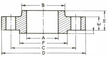
| Drilling | |||||||||
|---|---|---|---|---|---|---|---|---|---|
| Nominal Bore | Dia. (D) |
Thick. (E) |
Dia. (F) |
Dia. (B) |
Dia. (A) |
Height1 (H) |
Nbr | Holes | Dia. (C) |
| 1/2" | 90 | 9.6 | 35.05 | 30 | 22.2 | 14 | 4 | 15.87 | 60.3 |
| 3/4" | 100 | 11.2 | 42.93 | 38 | 27.7 | 14 | 4 | 15.87 | 69.9 |
| 1" | 110 | 12.7 | 50.80 | 49 | 34.5 | 16 | 4 | 15.87 | 79.4 |
| 1 1/4" | 115 | 14.3 | 63.50 | 59 | 43.2 | 19 | 4 | 15.87 | 88.9 |
| 1 1/2" | 125 | 15.9 | 73.15 | 65 | 49.5 | 21 | 4 | 15.87 | 98.4 |
| 2" | 150 | 17.5 | 91.95 | 78 | 61.9 | 24 | 4 | 19.05 | 120.7 |
| 2 1/2" | 180 | 20.7 | 104.65 | 90 | 74.6 | 27 | 4 | 19.05 | 139.7 |
| 3" | 190 | 22.3 | 127.00 | 108 | 90.7 | 29 | 4 | 19.05 | 152.4 |
| 3 1/2" | 215 | 22.3 | 139.70 | 122 | 103.4 | 30 | 8 | 19.05 | 177.8 |
| 4" | 230 | 22.3 | 157.22 | 135 | 116.1 | 32 | 8 | 19.05 | 190.5 |
| 5" | 255 | 22.3 | 185.67 | 164 | 143.8 | 35 | 8 | 22.22 | 215.9 |
| 6" | 280 | 23.9 | 215.90 | 192 | 170.7 | 38 | 8 | 22.22 | 241.3 |
| 8" | 345 | 27.0 | 269.75 | 246 | 221.5 | 43 | 8 | 22.22 | 298.5 |
| 10" | 405 | 28.6 | 323.85 | 305 | 276.2 | 48 | 12 | 25.40 | 362.0 |
| 12" | 485 | 30.2 | 381.00 | 365 | 327.0 | 54 | 12 | 25.40 | 431.8 |
| 14" | 535 | 33.4 | 412.75 | 400 | 359.2 | 56 | 12 | 28.57 | 476.3 |
| 16" | 595 | 35.0 | 469.90 | 457 | 410.5 | 62 | 16 | 28.57 | 539.8 |
| 18" | 635 | 38.1 | 533.40 | 505 | 461.8 | 67 | 16 | 31.75 | 577.9 |
| 20" | 700 | 41.3 | 584.20 | 559 | 513.1 | 71 | 20 | 31.75 | 635.0 |
| 24" | 815 | 46.1 | 692.15 | 663 | 616.0 | 81 | 20 | 34.92 | 749.3 |
1,6mm raised face not included in the E & H dimensions
The dimensions are in millimeters
Source : ASME B16.5 - 2007
300 Lbs
| Drilling | |||||||||
|---|---|---|---|---|---|---|---|---|---|
| Nominal Bore | Dia. (D) |
Thick. (E) |
Dia. (F) |
Dia. (B) |
Dia. (A) |
Height1 (H) |
Nbr | Holes | Dia. (C) |
| 1/2" | 21.3 | 12.7 | 35.05 | 38 | 22.2 | 21 | 4 | 15.87 | 66.7 |
| 3/4" | 26.7 | 14.3 | 42.93 | 48 | 27.7 | 24 | 4 | 19.05 | 82.6 |
| 1" | 33.4 | 15.9 | 50.80 | 54 | 34.5 | 25 | 4 | 19.05 | 88.9 |
| 1 1/4" | 42.2 | 17.5 | 63.50 | 64 | 43.2 | 25 | 4 | 19.05 | 98.4 |
| 1 1/2" | 48.3 | 19.1 | 73.15 | 70 | 49.5 | 29 | 4 | 22.22 | 114.3 |
| 2" | 60.3 | 20.7 | 91.95 | 84 | 61.9 | 32 | 8 | 19.05 | 127.0 |
| 2 1/2" | 73.0 | 23.9 | 104.65 | 100 | 74.6 | 37 | 8 | 22.22 | 149.2 |
| 3" | 88.9 | 27.0 | 127.00 | 117 | 90.7 | 41 | 8 | 22.22 | 168.3 |
| 3 1/2" | 101.6 | 28.6 | 139.70 | 133 | 103.4 | 43 | 8 | 22.22 | 184.2 |
| 4" | 114.3 | 30.2 | 157.22 | 146 | 116.1 | 46 | 8 | 22.22 | 200.0 |
| 5" | 141.3 | 33.4 | 185.67 | 178 | 143.8 | 49 | 8 | 22.22 | 235.0 |
| 6" | 168.3 | 35.0 | 215.90 | 206 | 170.7 | 51 | 12 | 22.22 | 269.9 |
| 8" | 219.1 | 39.7 | 269.75 | 260 | 221.5 | 60 | 12 | 25.40 | 330.2 |
| 10" | 273.0 | 46.1 | 323.85 | 321 | 276.2 | 65 | 16 | 28.57 | 387.4 |
| 12" | 323.8 | 49.3 | 381.00 | 375 | 327.0 | 71 | 16 | 31.75 | 450.8 |
| 14" | 355.6 | 52.4 | 412.75 | 425 | 359.2 | 75 | 20 | 31.75 | 514.4 |
| 16" | 406.4 | 55.6 | 469.90 | 483 | 410.5 | 81 | 20 | 34.92 | 571.5 |
| 18" | 457.0 | 58.8 | 533.40 | 533 | 461.8 | 87 | 24 | 34.92 | 628.6 |
| 20" | 508.0 | 62.0 | 584.2td> | 587 | 513.1 | 94 | 24 | 34.92 | 685.8 |
| 24" | 610.0 | 68.3 | 692.15 | 702 | 616.0 | 105 | 24 | 41.27 | 812.8 |
1,6mm raised face not included in the E & H dimensions
The dimensions are in millimeters
Source : ASME B16.5 - 2007
600 Lbs
| Drilling | |||||||||
|---|---|---|---|---|---|---|---|---|---|
| Nominal Bore | Dia. (D) |
Thick. (E) |
Dia. (F) |
Dia. (B) |
Dia. (A) |
Height1 (H) |
Nbr | Holes | Dia. (C) |
| 1/2" | 21.3 | 14.3 | 35.05 | 38 | 22.2 | 22 | 4 | 15.87 | 66.7 |
| 3/4" | 26.7 | 15.9 | 42.93 | 48 | 27.7 | 25 | 4 | 19.05 | 82.6 |
| 1" | 33.4 | 17.5 | 50.80 | 54 | 34.5 | 27 | 4 | 19.05 | 88.9 |
| 1 1/4" | 42.2 | 20.7 | 63.50 | 64 | 43.2 | 29 | 4 | 19.05 | 98.4 |
| 1 1/2" | 48.3 | 22.3 | 73.15 | 70 | 49.5 | 32 | 4 | 22.22 | 114.3 |
| 2" | 60.3 | 25.4 | 91.95 | 84 | 61.9 | 37 | 8 | 19.05 | 127.0 |
| 2 1/2" | 73.0 | 28.6 | 104.65 | 100 | 74.6 | 41 | 8 | 22.22 | 149.2 |
| 3" | 88.9 | 31.8 | 127.00 | 117 | 90.7 | 46 | 8 | 22.22 | 168.3 |
| 3 1/2" | 101.6 | 35.0 | 139.70 | 133 | 103.4 | 49 | 8 | 25.40 | 184.2 |
| 4" | 114.3 | 38.1 | 157.22 | 152 | 116.1 | 54 | 8 | 25.40 | 215.9 |
| 5" | 141.3 | 44.5 | 185.67 | 189 | 143.8 | 60 | 8 | 28.57 | 266.7 |
| 6" | 168.3 | 47.7 | 215.90 | 222 | 170.7 | 67 | 12 | 28.57 | 292.1 |
| 8" | 219.1 | 55.6 | 269.75 | 273 | 221.5 | 76 | 12 | 31.75 | 349.2 |
| 10" | 273.0 | 63.5 | 325.85 | 343 | 276.2 | 86 | 16 | 34.92 | 431.8 |
| 12" | 323.8 | 66.7 | 381.00 | 400 | 327.0 | 92 | 20 | 34.92 | 489.0 |
| 14" | 355.6 | 69.9 | 412.75 | 432 | 359.2 | 94 | 20 | 38.10 | 527.0 |
| 16" | 406.4 | 76.2 | 469.90 | 495 | 410.5 | 106 | 20 | 41.27 | 603.2 |
| 18" | 457.0 | 82.6 | 533.40 | 546 | 461.8 | 117 | 20 | 44.45 | 654.0 |
| 20" | 508.0 | 88.9 | 584.20 | 610 | 513.1 | 127 | 24 | 44.45 | 723.9 |
| 24" | 610.0 | 101.6 | 692.15 | 718 | 616.0 | 140 | 24 | 50.80 | 838.2 |
6,4 raised face not included in the E & H dimensions
The dimensions are in millimeters
Source : ASME B16.5 - 2007